Week 4
Assignment
- Create an electronic circuit that performs an action (at least blinking). Do not use a breadboard for connections.
- Possible Variants:
- Assemble (or even mill) a PCB for a simple blinking circuit.
- Build a blinker using discrete components on a universal PCB or as a freeform circuit.
- Create a blinker using an Arduino (we will cover this more next week; you can take inspiration from the Arduino Projects Book). Ensure the Arduino is placed in sockets so it can be removed.
The project
I have decided to use templated LED chaser with timer 555. This looked like a challenge for me (and it was) since I have very little experience with soldering.
Circuit diagram

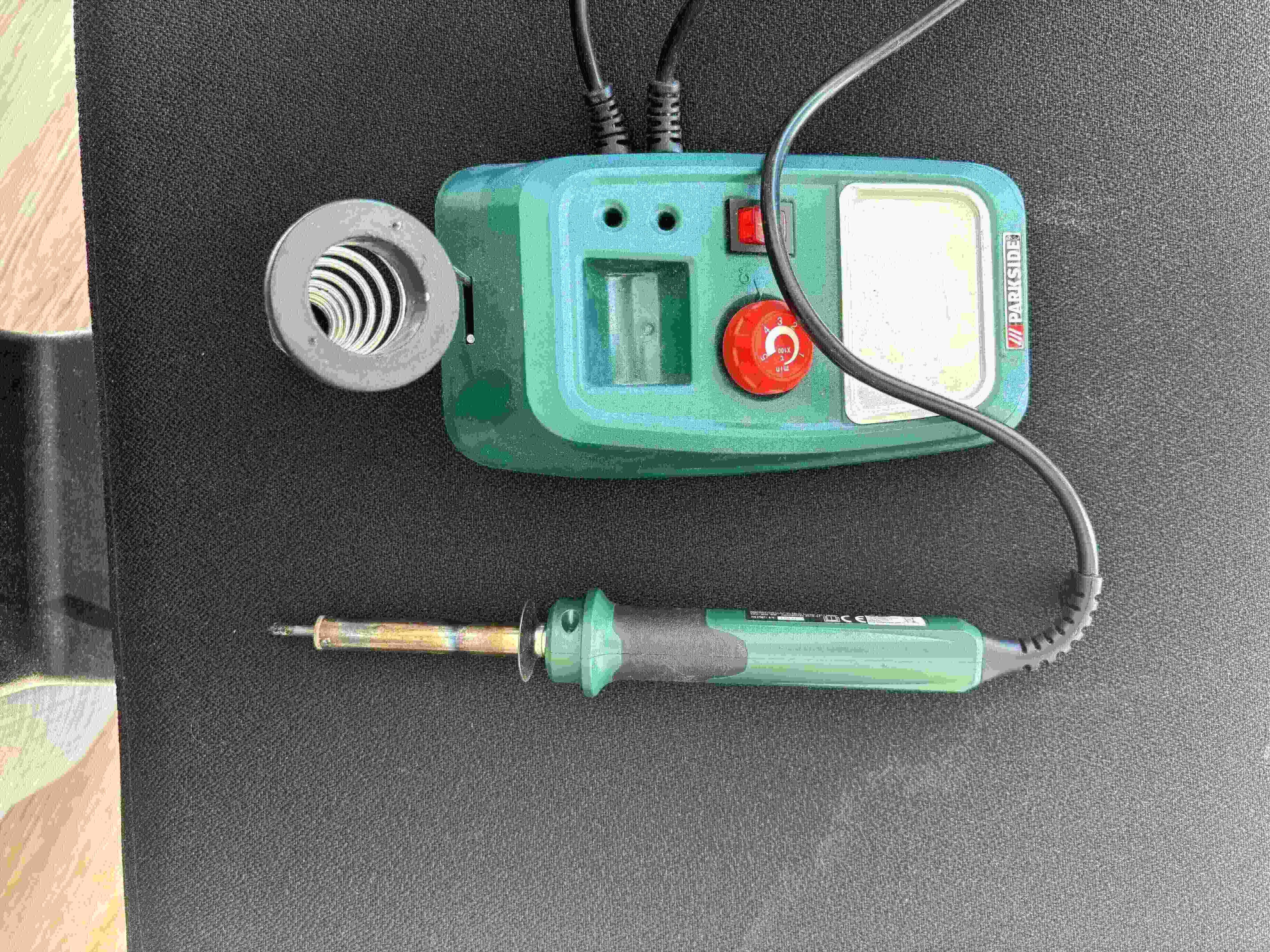
Solder
Solder choice
I overestimated my abilities and thought I could do it easily at home, but it turned out to be a poor choice.
Starting with the hardest issue
I had little to no experience with soldering and I started with the main chip.

Then I got better with all the resistors and the second chip looked much better.
Finished with soldering
The final result turned out to be pretty ok at the first glance.
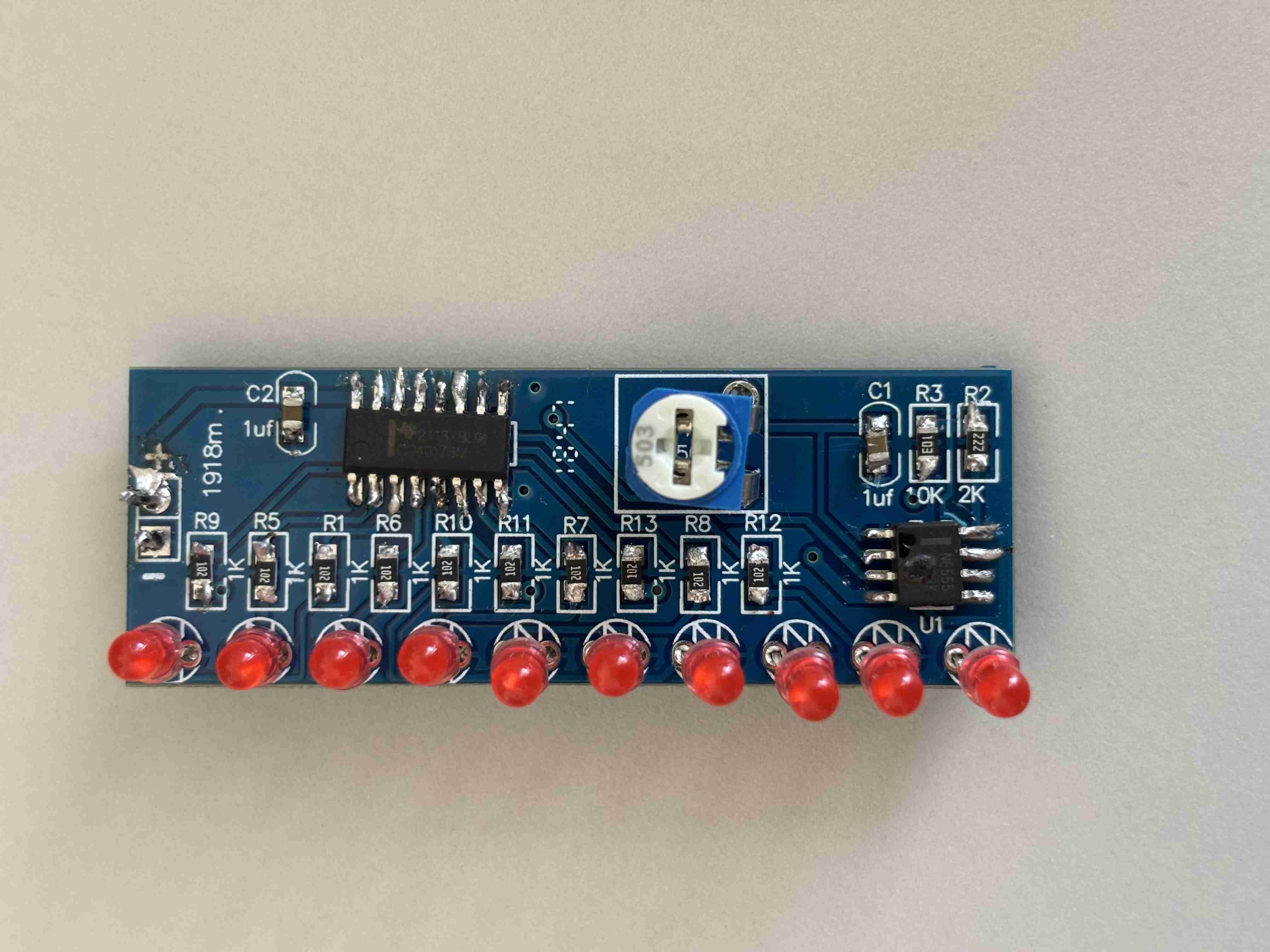
When I ran the first test of the LED chaser I supplied 12 V source and only one LED was turned on.

I still do not understand the behaviour. The current must have gone through the circuit, otherwise the LED light wouldn't have been on. Everytime I unplugged and plugged again the source, the next light turned on and the previous one turned off. When I was wiggling the source I got LED chaser for a brief moment. After a while the chip overheated and burnt.


Tips
- When you have no or little experience with soldering, do it in the labs. And use smaller solder (experienced user would've done even with the bigger one)
- Start with easier things (like resistors) and work yourself up to chips.
- The solder burns finger even on very close proximity without actually touching the solder.